Power Diagnostics
Power Diagnostics
Screen Overview
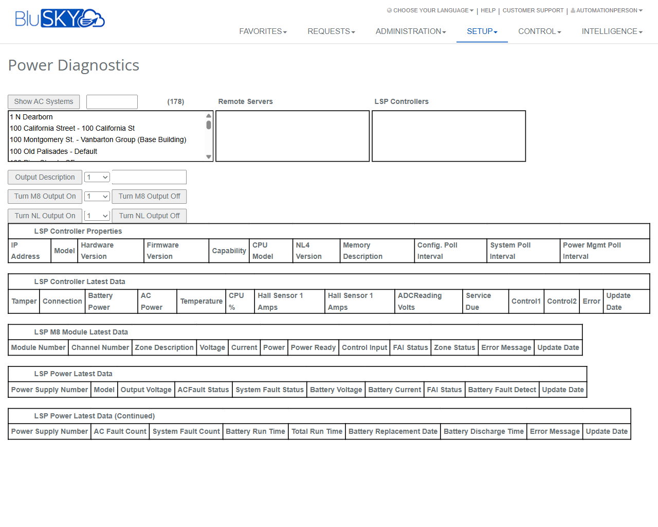
The Power Diagnostics screen provides real‑time visibility into LSP controllers and their associated power systems. Administrators and technicians can select a site, remote server, and controller to view controller properties, latest status metrics, module data, and power‑supply health. The screen also exposes safe controls to toggle specific M8 and NL output channels for testing and troubleshooting.
Field Definitions
| Field Label | Definition | Notes |
|---|---|---|
| Show AC Systems | Toggles display of AC systems in the site list. | When enabled, the list includes AC system entries; useful for large campuses. |
| Search (beside Show AC Systems) | Text search to filter the site/AC system list. | Filters as you type; partial matches supported. |
| Site/AC System List | Multi-line list of available buildings/sites or AC systems. | Select an entry to scope the Remote Servers and Controllers lists. |
| Remote Servers | List of remote servers associated with the selected site. | Select a server to see the controllers it hosts. |
| LSP Controllers | List of LSP controllers available on the selected server. | Choose a controller to load its properties and live data. |
| Output Description | Displays the descriptive label for the selected output channel. | Read-only; depends on the controller configuration. |
| Output Port Selector | Numeric selector used with Output Description. | Select an output number to view its description. |
| Turn M8 Output On | Sends a command to activate a selected M8 output channel. | Requires M8 Output Selector to be set. Control permission required. |
| M8 Output Selector | Numeric selector for the M8 output channel to control. | Typical range 1–8 per module; actual range depends on hardware. |
| Turn M8 Output Off | Sends a command to deactivate a selected M8 output channel. | Requires M8 Output Selector to be set. |
| Turn NL Output On | Sends a command to activate a selected NL output channel. | Requires NL Output Selector to be set. |
| NL Output Selector | Numeric selector for the NL output channel to control. | Actual range is controller‑dependent. |
| Turn NL Output Off | Sends a command to deactivate a selected NL output channel. | Requires NL Output Selector to be set. |
| IP Address | Network address of the selected LSP controller. | From “LSP Controller Properties.” Read-only. |
| Model | Controller model identifier. | Read-only. |
| Hardware Version | Hardware revision of the controller. | Read-only. |
| Firmware Version | Firmware revision running on the controller. | Read-only; verify compatibility when troubleshooting. |
| Capability | Feature set supported by the controller. | Read-only; may reflect licensed options. |
| CPU Model | Processor type in the controller. | Read-only. |
| NL4 Version | Version of the NL4 subsystem. | Read-only. |
| Memory Description | Memory capacity/descriptor. | Read-only. |
| Config. Poll Interval | Interval at which configuration is polled. | Read-only; affects refresh frequency of configuration data. |
| System Poll Interval | Interval at which system status is polled. | Read-only; impacts “Latest Data” update cadence. |
| Power Mgmt Poll Interval | Interval at which power metrics are polled. | Read-only. |
| Tamper | Tamper status of the controller enclosure. | From “LSP Controller Latest Data.” |
| Connection | Online/offline connection state. | Read-only. |
| Battery Power | Indicates battery power presence/health. | Read-only. |
| AC Power | Indicates AC mains power presence/health. | Read-only. |
| Temperature | Internal controller temperature. | Units per controller settings. |
| CPU % | Current CPU utilization. | Useful for load diagnostics. |
| Hall Sensor 1 Amps | Current reading from Hall sensor 1. | Read-only. |
| Hall Sensor 2 Amps | Current reading from Hall sensor 2. | Label may appear truncated depending on screen width. |
| ADC Reading Volts | Analog-to-digital converter voltage reading. | Read-only. |
| Service Due | Indicates if scheduled service is due. | Based on controller counters/policy. |
| Control1 | State of control line 1. | Read-only. |
| Control2 | State of control line 2. | Read-only. |
| Error | Current controller error text/code. | Clears when condition resolves. |
| Update Date (Controller) | Timestamp of last controller status update. | Read-only; helps identify stale data. |
| Module Number | Identifier of the M8 module reporting. | From “LSP M8 Module Latest Data.” |
| Channel Number | Output/input channel within the module. | Read-only in this table. |
| Zone Description | Friendly name of the zone/channel. | Read-only; configured elsewhere. |
| Voltage | Measured voltage for the channel. | Read-only. |
| Current | Measured current for the channel. | Read-only. |
| Power | Calculated power for the channel. | Read-only. |
| Power Ready | Indicates if the channel is ready/armed. | Read-only. |
| Control Input | State of control input tied to the channel. | Read-only. |
| FAI Status | Fire Alarm Interface status. | Read-only. |
| Zone Status | Overall zone/channel status. | Read-only. |
| Error Message (Module) | Channel/module error text/code. | Read-only. |
| Update Date (Module) | Timestamp of last module data update. | Read-only. |
| Power Supply Number | Identifier of the power supply unit (PSU). | Appears in both power tables. |
| Model (Power) | PSU model identifier. | Read-only. |
| Output Voltage | PSU output voltage. | Read-only. |
| AC Fault Status | AC input fault state. | Read-only. |
| System Fault Status | Overall PSU fault state. | Read-only. |
| Battery Voltage | Measured backup battery voltage. | Read-only. |
| Battery Current | Measured battery current. | Read-only. |
| FAI Status (Power) | FAI status as reported by PSU. | Read-only. |
| Battery Fault Detect | Battery fault indicator. | Read-only. |
| Update Date (Power) | Timestamp of last PSU data update. | Read-only. |
| AC Fault Count | Cumulative number of AC fault events. | From “LSP Power Latest Data (Continued).” |
| System Fault Count | Cumulative number of system fault events. | Read-only. |
| Battery Run Time | Elapsed time on battery during last/active event. | Units controller‑dependent. |
| Total Run Time | Aggregate runtime of the PSU/controller. | Read-only. |
| Battery Replacement Date | Last recorded battery replacement date. | Admin-maintained or device‑reported. |
| Battery Discharge Time | Duration of last discharge event. | Read-only. |
| Error Message (Power) | PSU error text/code. | Read-only. |
| Update Date (Power Continued) | Timestamp for continued power metrics. | Read-only. |
Screen Actions and Functions
- Select Site/AC System – Scopes the Remote Servers and LSP Controllers lists.
- Select Remote Server – Filters controllers to those hosted on the chosen server.
- Select LSP Controller – Loads Properties, Latest Data, Module data, and Power data for that device.
- Output Description – Shows the label for the output selected in Output Port Selector.
- Turn M8 Output On/Off – Activates or deactivates the M8 output chosen in M8 Output Selector.
- Turn NL Output On/Off – Activates or deactivates the NL output chosen in NL Output Selector.
- Adjust Poll Intervals (view only) – Displays current polling cadence used by the system for updates.
Usage Instructions & Examples
How to view a controller’s live status
- In Site/AC System List, select the desired building or system.
- Choose the appropriate Remote Server.
- Select an LSP Controller.
- Review LSP Controller Properties and LSP Controller Latest Data to confirm connection, power, temperature, and errors.
How to test an M8 output channel
- Select the site, server, and controller as above.
- In M8 Output Selector, choose the channel number to test.
- Click Turn M8 Output On and observe the Module Latest Data (Voltage/Current/Zone Status) for change.
- Click Turn M8 Output Off to return the channel to its normal state.
- Use Output Description to confirm you are acting on the correct labeled output.
How to verify power‑supply health
- Select the target controller.
- In LSP Power Latest Data, check AC Fault Status and Battery Voltage.
- Open LSP Power Latest Data (Continued) to review Battery Run Time and Battery Replacement Date.
- If AC Fault Status is active or Battery Voltage is below expected levels, schedule maintenance.
System Behaviors and Edge Cases
- Lists are context dependent: selecting a site filters Remote Servers, which then filters LSP Controllers.
- Control buttons are disabled or will fail gracefully if no controller and channel are selected.
- Commands are sent to the single selected controller; multi-select is not supported for output control.
- Poll intervals shown in Properties determine how frequently the latest data tables refresh.
- Update Date fields indicate the last successful poll; if timestamps lag significantly, the controller or network may be unavailable.
- Some metrics may appear blank if the device firmware does not support them.
- Service Due indicates maintenance due based on device counters or policy; it does not block operations.
- Output commands may be rate‑limited; rapid toggling can be ignored to protect hardware.
- If permissions are insufficient, control actions are hidden or return an authorization error while read-only data remains accessible.
Permissions
- Screen access: Global Administrators and Tenant Administrators with device management rights.
- Read-only viewing: Operators/Technicians with ViewDiagnostics permission.
- Output control actions (Turn M8/NL On/Off): Requires ControlOutputs or equivalent elevated permission.
- Editing of controller configuration is not available on this screen; use controller setup permissions elsewhere.
Linked Workflows
- LSP Controller Setup – Configure controllers, modules, and output labels used by this screen.
- Sites/AC Systems – Manage sites and server associations that populate the selection lists.
- Alarm and Event History – Investigate faults indicated by Error, AC Fault Status, or Battery Fault Detect.
- Notifications/Rules – Create alerts for power or tamper conditions observed here.
- Work Orders/Maintenance – Schedule service when Service Due or battery replacement indicators are present.
Reference Image Links