Creating a Portal
Overview
In this lesson we discuss how create all of the necessary components of a Portal, including creating and configuring an Input, Output and Reader.
Creating an Input
Input are simple electrical circuits that provide information to the access control system. Inputs can range from a simple door contact to high tech zone motion detection.
Create an Input
- Navigate to Inputs. Main Menu-> Setup-> System Setup-> Input
- Use the
 icon on the lower-left side to create a new Input.
 - Pick the Controller that manages the Input.
- Pick the SIO Board or the Controller the Input is physically attached to.
- ***Note:***If the Input is connected directly to a Controller the Controller and SIO Board fields will have the same name.
- Next, choose a Name for the Input.
- ***Note:***Using good names can make the process of servicing and debugging much easier.
- Select the Input Number that corresponds with where the Input is connected to on the SIO Board.
- Note: The physical board should be labeled with these numbers, if not use the official board documentation.
- Choose the Input Normal State from the dropdown menu.
- Set the Debounce.
- Set the Hold Time.
- Confirm the entry with the
 button or because of the nature of this job we provide a
  button to move onto the next entry quickly.
- Note: There are many more ways to configure a Controller the More...
 option will expand these options. This option should only be explored by trained technicians.

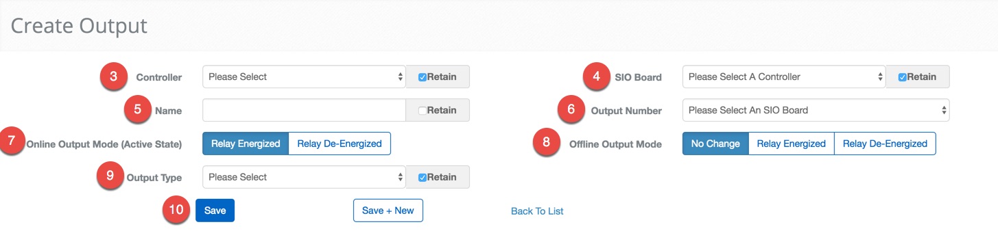
Creating an Output
Outputs allow the access control system to influence the physical world. Outputs can be anything from horns and alarms to electromagnetic locks.
Create an Output
- Navigate to Outputs. Main Menu-> Setup-> System Setup-> Output
- Use the icon on the lower left side to create a new Output.
- Pick the Controller that will be used to manage the Output.
- Then select the SIO Board the Output is attached to.
- ***Note:***In some cases, the SIO Board and Controller will be the same.
- Next, choose a Name for the Output.
- ***Note:***Using good names can make the process of servicing and debugging much easier.
- Select the Output Number that corresponds with Output.
- Note: This is the number that corresponds with which connection is used on the board.
- Click on either the Relay Energized or the Relay De-Energized button for the Online Output Mode. This will determine how the Output should behave during normal operation.
- Ex. A magnetic lock would "Relay De-Energized" to cause the magnet to become inactive and release the door.
- Click on either No Change, Relay Energized or Relay De-Energized button to set the Offline Output Mode. This will determine how the Output behaves when it is unable to communicate with the Controller and is unable to verify credentials.
- Select the type of the Output from the Output Type drop-down menu.
- Confirm the entry with the button, alternatively, we provide a button to move onto the next entry quickly.
Creating a Reader
Readers are any devices that read and validate credentials to allow access.
Create a Reader
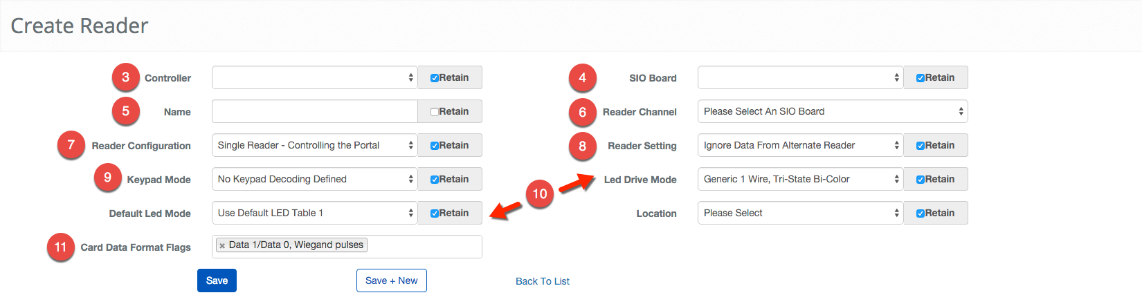
Wiegand Reader
- Navigate to Readers. Main Menu-> Setup-> System Setup-> Readers
- Use the icon in the lower left side to create a new Reader.
- First, pick the Controller that will manage the Reader.
- Select the SIO Board the Reader is attached.
- ***Note:***In some situations the SIO Board and Controller will be the same.
- Enter a name for the Reader in the Name text field.
- ***Note:***Using good names can make the process of servicing and debugging much easier.
- Select the Reader Channel that corresponds with the Reader port on the SIO Board or Controller.
- Note: This is the number that corresponds with which connection is used on the board.
- Choose the Reader Configuration.
- Choose the Reader Setting from the dropdown menu.
- Choose the Keypad Mode.
- Select the appropriate LED Drive Mode and Default LED Mode.
- Click in the Card Data Format Flags field to bring up list of applicable Format Flags.
- Confirm the entry with the button or because of the nature of this operation we provide a button to move onto the next entry quickly.
OSDP Reader
- Navigate to Readers. Main Menu-> Setup-> System Setup-> Readers
- Use the icon in the lower left side to create a new Reader.
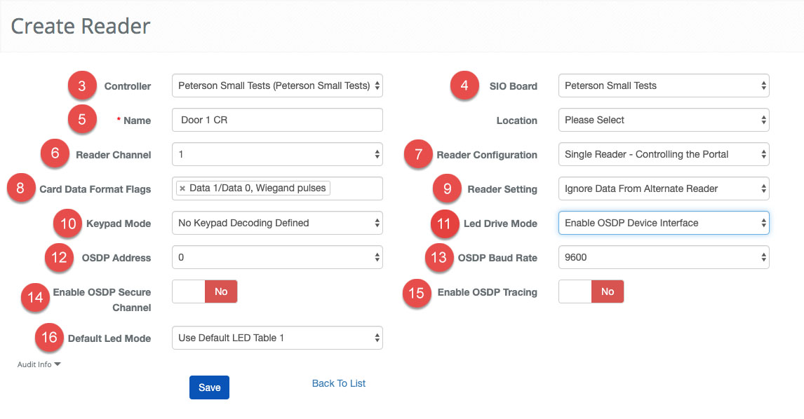
- First, pick the Controller that will manage the Reader.
- Select the SIO Board the Reader is attached.
- ***Note:***In some situations the SIO Board and Controller will be the same.
- Enter a name for the Reader in the Name text field.
- ***Note:***Using good names can make the process of servicing and debugging much easier.
- Select the Reader Channel that corresponds with the Reader port on the SIO Board or Controller.
- Note: This is the number that corresponds with which connection is used on the board.
- Choose the Reader Configuration.
- Click in the Card Data Format Flags field to bring up list of applicable Format Flags.
- Choose the Reader Setting from the dropdown menu.
- Choose the Keypad Mode.
- Select the appropriate Led Drive Mode set to OSDP Device Interface
- OSDP Address - Select the channel the reader is configured for. Most single OSDP Readers are 0. You can purchase readers with different channel numbers, and there are reader configuration cards that will change the channel. If you do not know your channel start with 0 and work your way up. Note: WIth OSDP you can now "daisy-chain" 4 readers to a single reader port on the SIO board.
- Set the OSDP Baud Rate - 4 speed options 9600 (default) 19200, 38400, 115200
- Enable OSDP Secure Channel allows for secure communication from Controller to Reader
- Enable OSDP Tracing This should be set to "No" unless directed by BluB0X support. This setting will add OSDP reader information to Mercury debug logs, which would also need to be manually configured by BluB0X Support.
- Click in the Default LED Mode field to bring up list of applicable modes.
- Confirm the entry with the button or because of the nature of this operation we provide a button to move onto the next entry quickly.
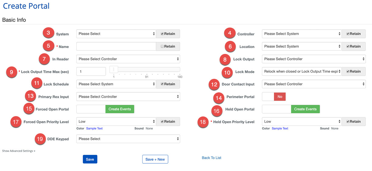
Creating a Portal
Portals are the grouping of devices that work together to secure entry or exit. A Portal will contain a combination of locks, inputs and sensors and assist in managing the access control system easily.
Create a Portal
- Log in and navigate to Portals. Main Menu-> Setup-> System Setup-> Portal
- Use the icon on the lower left side to create a new Portal.
- First, choose the System using the dropdown menu.
- Then choose which Controller will manage the Portal.
- Next, enter a Name for the Portal.
- ***Note:***Choose a descriptive name to make the management of the Portal easier in the future
- Select Location
- Select the In Reader that will provide credentials to the AC System.
- Next, we assign the Lock Output that will be used to control the Portal.
- Set the Lock Output Time Max. This will determine how long the Output is in its unlocked state.
- Set the Lock Output Mode by choosing from the dropdown menu.
- Now, we must assign a Lock Schedule that will determine when the Portal is Locked.
- ***Note:***This must be a Device Schedule.
- Select the correct Door Contact Input to allow the Portal to report its state.
- Next, we will designate the Primary Rex Input using the dropdown menu.
- To complete Portal use the toggle to specify if the Portal should be treated as a Perimeter Portal or not.
- Set the behavior for Forced Open Portal events.
- **Note:**Forced Open and Held Open events will always create events. For more on the benefits of each configuration see, Forced Open and Held Open Alarms and Events
- Set the behavior for Held Open Portal events.
- Set the behavior for Forced Open Priority Level events.
- Set the behavior for Held Open Priority Level events.
- Select DDE Keypad floor.
- When finished use the
 button to finish or the to continue configuring Portals.
- Note: There are many more ways to configure a Portal, Show Advanced Settings option will expand these options.