Controller Hardware Configuration
Overview
This article will cover how to configure the Mercury controllers for a Access Control System.
For more information please refer to the complete documentation, found here: EP1502, EP1501, EP2500, MR52 , MR16in and MR16out.
Directions
- First , mount boards and power supply in cabinet or in there final location.
- Wire Power from power supply to power on EP1502, MR52, MR16in. Be sure to only provide one Earth Ground for the System to avoid ground loop problems.
- Black wire to Ground
- Red wire to Power (V IN)
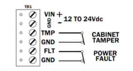

- On the EP1502 configure the Tamper and UPS monitoring, with a closed condition. If Tamper and UPS monitoring are not going to be used install a jumper wire here to close the circuit.
- Ensure that the EP1502 is set to 12V , if not set the jumper at J7 to the rightmost two pins. (The standard orientation is with the battery at the top.)
- ***Note:***Setting the jumper to PT(pass through) can seriously damage equipment, please consult card reader specifications to ensure that the card reader or other device can handle the power being supplied.
- ***Note:***If using the PT feature you must ensure that at least 20Vdc is being supplied to the board.
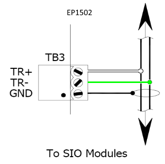
- Wire RS485
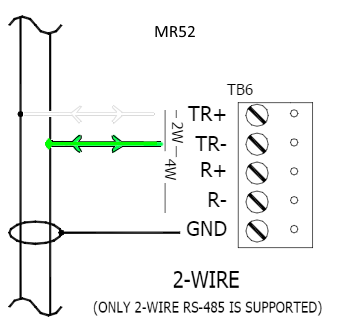
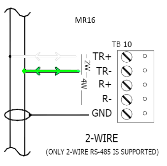
- Note: We will always use the White wire in TR+ and the Green Wire on TR-
- ***Note:***The MR52, MR16IN and MR16OUT will only support 2 wire configurations and require the jumper be placed on 2W at the J3 jumper
- For EP1502 RS485 points are at TB3 (SIO Port for 2-wire RS-485) on the board
- Note: Communication begins at the EP1502 and daisy chains to the other boards using a MUX8 as necessary.
- MR52 (TB6- SIO Port for 2-wire RS-485) Board also says RS485
- MR16IN (TB10) Board also says RS485
- MR16OUT (TB10) Board also says RS485
- Next, we will disable termination of the RS485 signal. This is our recommended configuration for more details please consult the full documentation for each of the devices.
- On the EP1502 and MR 52, the jumper should be unset at J5.
- On the MR16IN and MR16OUT the jumpers at J1 should be unset.
- Next, we will configure the MR 52s and MR 16s
- Each board will have eight dip switches. The first five switched S1-S5 are used for setting the address of the device and the last three, S6-S8 are used for determining the baud rate.
- We must address all of the boards connected to the system in series. The address switches work on a binary number system, for example if S1 and S2 are on it represents address 3. View Chart
 .
. - Note: is important to never assign a board address 0 as this is reserved for the EP1502.
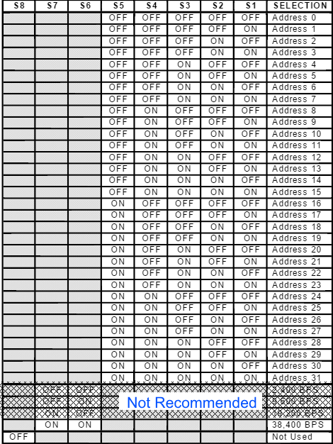
-
Next, we will set the baud rate. For all BluSKY configurations we will use a baud rate of 38400, which is configured with dip switches S6 and S7 in an on position.
-
When finished, see the Network Configuration for the EP1502 guide to complete the hardware's network configuration.