BluSKY System Configuration
Overview
In this demo we begin to configure BluSKY to use the hardware we have previously configured. We will begin by constructing the Customer, System and Facility records for the building. Once the base system configuration is done we will begin adding the individual hardware components to form two complete Portals.
If BluBØX has supplied the configuration this article may serve as a reference of all of the steps BluBØX has taken to create your demo. You are welcome to repeat this process for training or demonstration purposes.
Create a Customer
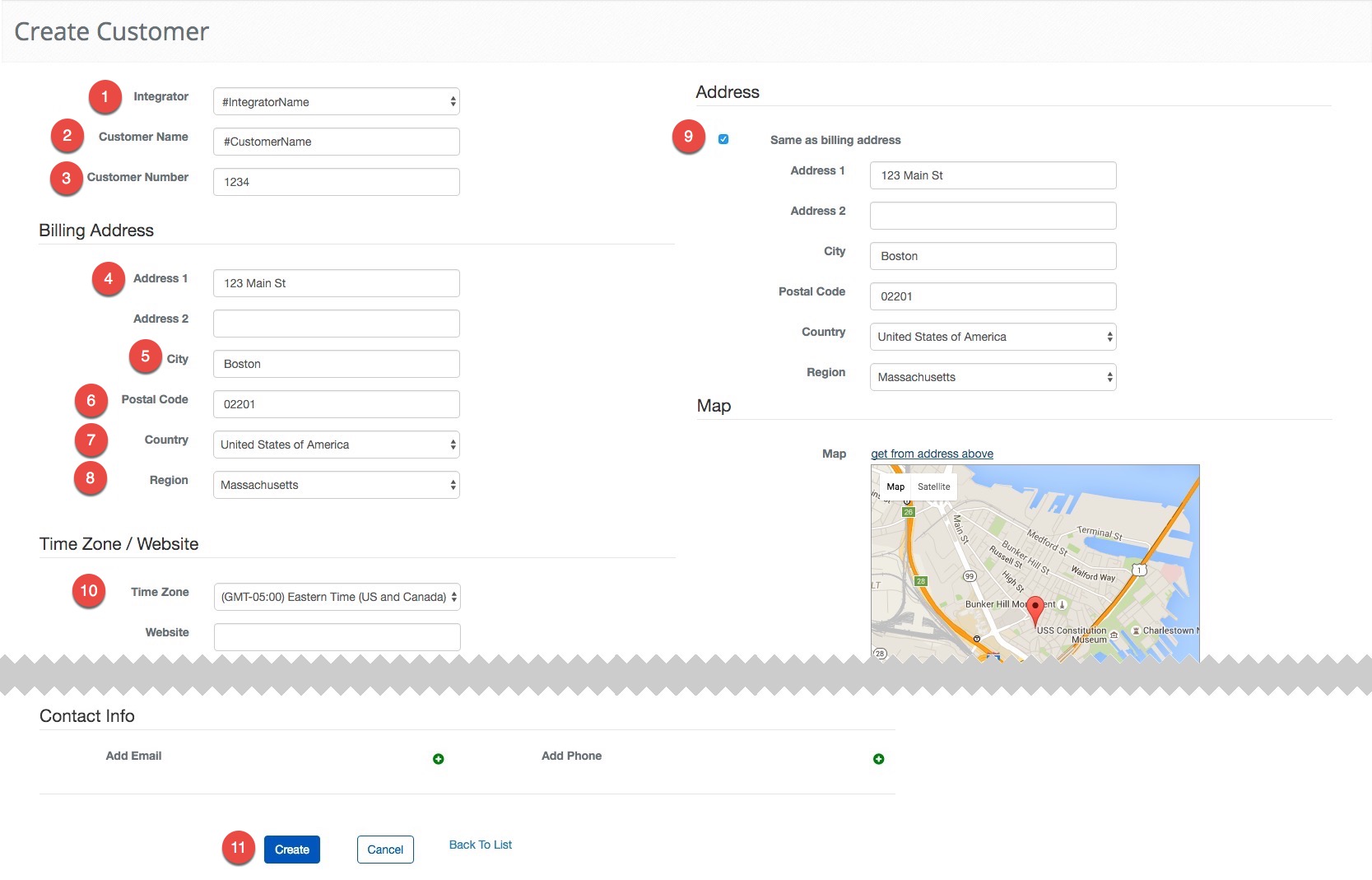
A Customer is the entity that will own one or more access control systems. By default, when a Customer is created a System and Facility are created automatically with the name of the Customer and their address. We are not going to use those entries in this article, so we can go through the entire process manually. Remember, only Integrators with the correct permissions can create Customers. We have provided a sample address to help pair fields with the instructions.
To begin, navigate to Customer creation. Main Menu-> Setup-> Facilities and Customers-> Customer Setup-> Create
 Click to Enlarge
- Select #IntegratorName from the drop-down menu.
- Enter #CustomerName for the Customer's Name
- Enter 1234 in the Customer Number text field.
- Enter **123 Main St.**into the Address 1 text field.
- Enter the Boston in the City text field.
- Enter 02201 in the Zip Code text field.
- Select the United States of America from the Country drop down menu.
- Select Massachusetts from the Region drop down menu.
- Check the "Same as billing address" radio button.
- Choose (GMT -05:00) Eastern Time(US and Canada) from the Time Zone drop down menu.
- Select the
 button to finish.
Create a System
The System is the basis of the entire configuration. This is the database record that Facilities, People, Schedules, Roles, and Access Levels are associated with. This is important because it allows you to group multiple Controllers under one System, regardless of physical location.
Start by navigating to System creation. Main Menu-> Setup-> System Setup-> System-> Create
Click to Enlarge
- Enter #SystemName for the name of the System.
- Select #IntegratorName from the Integrator drop down menu.
- Select #CustomerName from the Customer drop down menu.
- Next, toggle the Is Base Building System toggle to "Yes".
- Select the button to finish.
Create a Facility
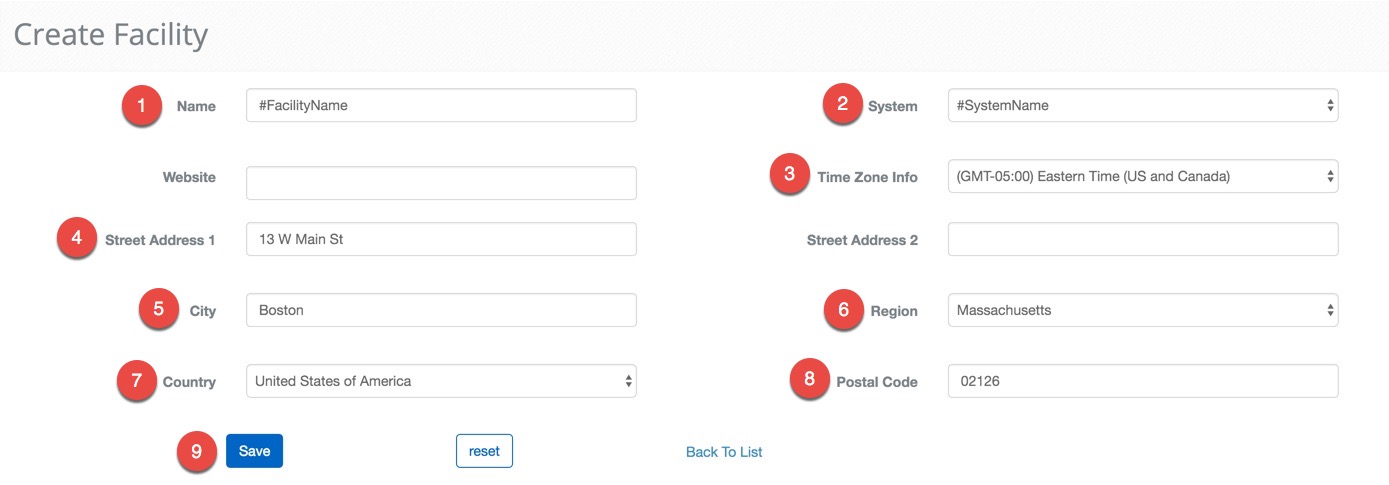
The Facility describes the physical building that contains the access control system. You can have multiple, geographically diverse, facilities connected to the same access control system, perfect for large campus installations.
Go to Facility Creation, Main Menu-> Setup-> Facilities and Customers-> Facility-> Create
 Click to Enlarge
- Enter #FacilityName as the name of the Facility.
- Select #SystemName from the System drop down menu.
- Choose (GMT -05:00) Eastern Time(US and Canada) from the Time Zone drop down menu.
- Enter the 13 W. Main Stin the Street Address 1 text field.
- Enter Boston for the City field.
- Set the Region to Massachusetts.
- Set the Country to United States of America.
- Enter 02126 as the Postal Code.
- Select the
 button to finish.
Create a Controller
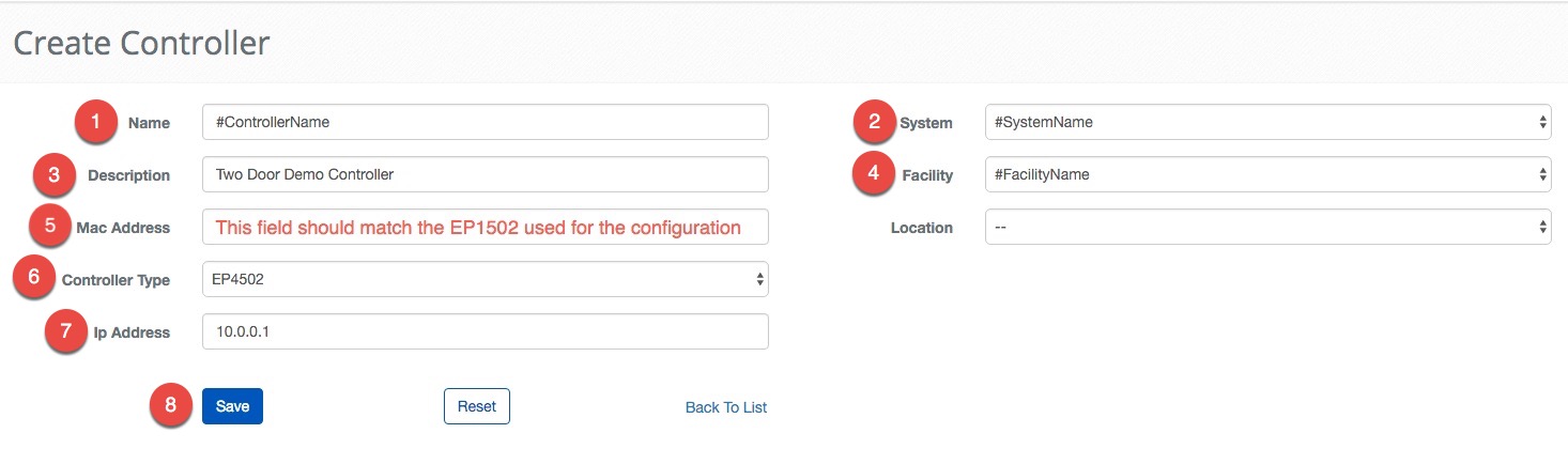
Controllers are the most important part of the hardware. It is the brain of the System and is a crucial part of connecting BluSKY to the physical world. Systems can and often do contain multiple Controllers, but for our simple two door system we are only configuring one controller.
Navigate to Controllers Creation. Main Menu-> Setup-> System Setup-> Controllers-> Create
 Click to Enlarge
- Enter the #ControllerName for the Name of the Controller.
- Select #SystemName using the System drop down menu.
- Enter "Two Door Demo Controller" in the Description text field.
- Select #FacilityName from the Facility drop down menu.
- Enter the MAC Address from an EP1502 in the MAC Address of the Controller.
- ***Note:***This address must begin with "MAC".
- Choose EP1502 from the Controller Type drop down menu.
- Enter 10.0.0.1 for the IP Addressfor the Controller. BluSKY does not use the IP address but can be helpful for diagnosing network issues.
- Select the button to finish.
***Note:***Frequently, this is the point where you would add additional SIO Boards. For this example we are only going to be using only one EP1502 so there is no need to add additional SIO boards.
Create Four Inputs
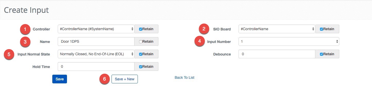
Inputs allow the hardware to interpret the physical world by using simple circuits. We will first create two Inputs to be used as Door Position Sensors(DPS). These Inputs will use a simple circuit to indicate whether the door is closed or not. Then we will build two simple Request To Exit (REX) Inputs that allow the door to open without having to supply a credential. REXs are very common in installations to normalize and record the exit events.
Navigate to Input creation. Main Menu-> Setup-> System Setup-> Input-> Create
 Click to Enlarge
- Select #ControllerName from the Controller drop down menu.
- Select #ControllerName from the SIO Board drop down menu. This is the same because we are using the connections on the EP1502.
- Name this Input "Door 1 DPS" in the Name text field.
- Select 1 for the Input Number, this Input Number represents the numbered physical connection to the Controller or SIO Board.
- Choose Normal Closed, No End-Of-Line (EOL) for the Input Normal State from the dropdown menu. This tells the system that the normal state of this circuit is closed and the circuit being interrupted represents an event.
- Click the
 button to move onto the next entry. By clicking this button all fields that have the Retain box checked will be carried to the next configuration.
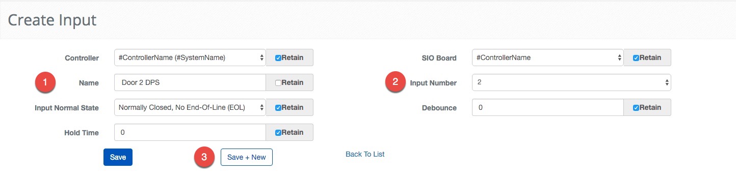
The next Input is very similar with two small changes, the name for the next Input will be "Door 2 DPS" and the Input Number will be 2. To ensure a proper configuration we have included the above instructions with the updated fields.
 Click to Enlarge
Some fields are retained from the previous configuration.
- Name this Input "Door 2 DPS" in the Name text field.
- Select 2 for the Input Number.
- Click the button to move onto the next entry.
We have both DPS Inputs configured now. Next, we will move onto setting up the REXs. Once again we leverage the "Save + New" feature so we only change the Name, Input Number and Input Normal State. The rest of the configuration is retained from the previous steps.
 Click to Enlarge
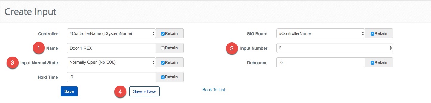
Some fields are retained from the previous configuration.
- Name this Input "Door 1 REX" in the Name text field.
- Select 3 for the Input Number.
- Choose Normal Open, (No EOL) for the Input Normal State from the dropdown menu.
- Click the button to move onto the next entry.
 Click to Enlarge
Some fields are retained from the previous configuration.
- Name this Input "Door 2 REX" in the Name text field.
- Select 4 for the Input Number.
- Choose Normal Open, (No EOL) for the Input Normal State from the dropdown menu.
- Click the button to finish the Input configuration.
Create Two Outputs
Outputs are pieces of hardware that are able to activate sirens, motors, lights and much more, but for this example our Outputs will be used to control the locks of the portal. We are configuring hypothetical outputs in the database. If you are using physical locks you may have to make some adjustments to match the equipment you are using.
Start configuring Outputs by navigating to Output creation. Main Menu-> Setup-> System Setup-> Output-> Create
 Click to Enlarge
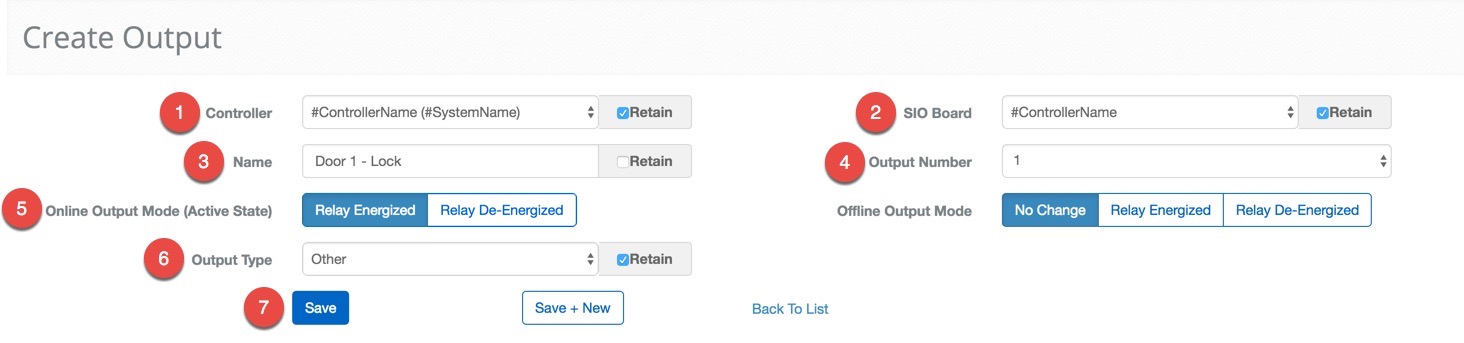
- Select #ControllerName from the Controller drop down menu.
- Select #ControllerName from the SIO Board drop down menu.
- Name the Output "Door 1 - Lock" using the Name text field.
- Select 1 for the Output **Number.**This is where the physical connection is made ot the board.
- Click the Relay Energized buttonfor the Online Output Mode.
- Select Other from the Output Type drop down menu.
- If you are using physical locks adjust this setting to match the drive mode of the lock.
- Click the button to move onto the next entry quickly.
Now to configure the second doors Output. All of the settings will stay the same except the Output Number and Name, coincidentally only the fields that do not have the Retain box checked by default.
 Click to Enlarge
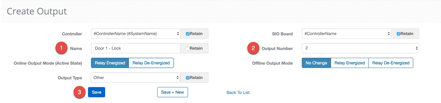
Some fields are retained from the previous configuration.
- Name the Output "Door 2 - Lock" using the Name text field.
- Select 2 for the Output Number.
- Click the button to finish the Output configuration.
Create Two Readers
Readers are used to read credentials. In this case we will be setting up a card reader, but the principle extends to keypads, Person Readers, and other biometric devices, including our patent pending Person Reader.
To begin, navigate to Reader creation. Main Menu-> Setup-> System Setup-> Readers-> Create
 Click to Enlarge
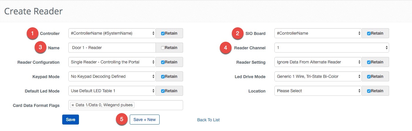
- Select #ControllerName from the Controller drop down menu.
- Select #ControllerName from the SIO Board drop down menu.
- Enter "Door 1 - Reader" in the Name text field.
- Select 1 for the Reader Channel.
- Note: This number corresponds to the physical connection used on the EP1502.
- ***Note:***We will be using the default settings for the rest of the fields.
- Confirm the entry with the button to move onto the next entry.
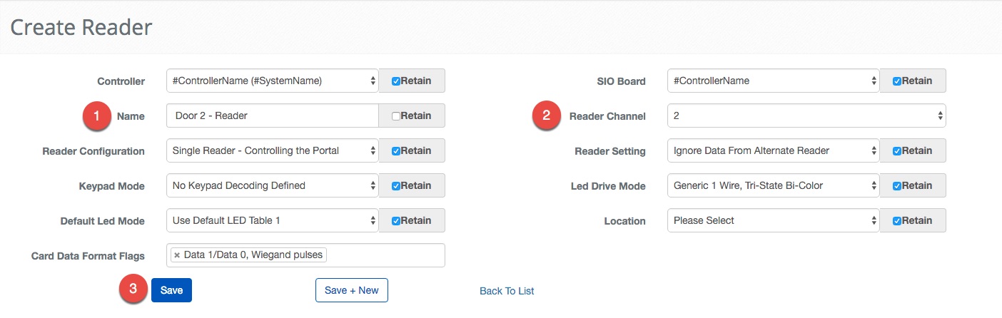
Now we will configure the other reader. As you might imagine by now it is only a matter of changing the Name and the Reader Channel.
 Click to Enlarge
Some fields are retained from the previous configuration.
- Enter "Door 2 - Reader" in the Name text field.
- Select 2 for the Reader Channel.
- Click the button to finish the Readers configuration.
Create Device Schedules
In this simple two door demo BluB0X is using globally available Device Schedules. For completeness, if you require a device schedule that is neither "always on" nor "always off" you will have to create a device schedule. If you are interested in making your own Device Schedule, please check out our Create a Device Schedule documentation.
Create Two Portals
Portals is where we group Outputs, Inputs and Readers together. By grouping all of the individual parts together, the process of controlling Portals becomes much easier.
Navigate to Portals creation. Main Menu-> Setup-> System Setup-> Portal-> Create
 Click to Enlarge
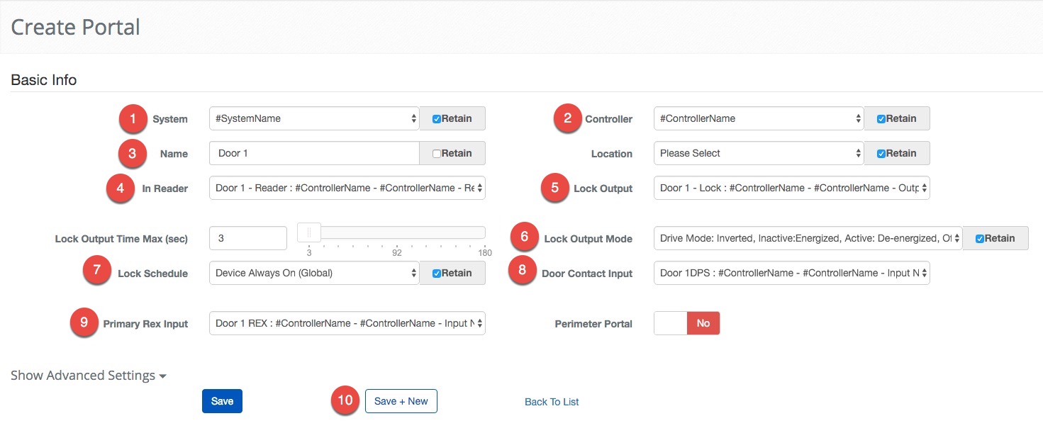
- Select #ControllerName from the Controller drop down menu.
- Select #ControllerName from the SIO Board drop down menu.
- Enter "Door 1" in the Name text field.
- Select the Door 1 - Reader from the In Reader drop down menu.
- Select Door 1 - Lock from the Lock Output drop down menu.
- Set the Lock Output Mode to Drive Mode: Inverted, Inactive:Energized, Active: De-energized.
- Select Device Always On(Global) from the Lock Schedule menu. This will tell the Portal to remain locked and will require a valid credential for entry.
- Select Door 1 - DPS for the Door Contact Input.
- Select Door 1 - REX for the Primary Rex Input using the dropdown menu.
- Use the button to continue onto the next Portal.
This example shows the importance of using good naming conventions for the different parts of the System. This process can be made infinitely more difficult if you are trying to remember if "Input 1" and "Input 2" are with this Portal or that one. The next set of instructions should feel very familiar. Once again, notice how the Retain feature provides short cuts for the some of the less exciting parts of making a configuration.
 Click to Enlarge
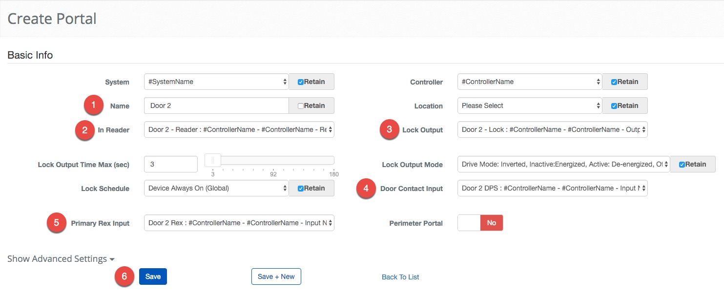
Some fields are retained from the previous configuration.
- Enter "Door 2" in the Name text field.
- Select the Door 2 - Reader from the In Reader drop down menu.
- Select Door 2 - Lock from the Lock Output drop down menu.
- Select Door 2 - DPS for the Door Contact Input.
- Select Door 2 - REX for the Primary Rex Input using the dropdown menu.
- Click the button to finish the Readers configuration.
Create Control Points
This last step is to configure two Control Points. This step is not required, but Control Points add an application layer to the Outputs. This makes the Output report its status to the Controller, an important part of our Real-Time functionality.
To begin, navigate to Control Point creation. Main Menu-> Setup-> System Setup-> Control Point-> Create
 Click to Enlarge
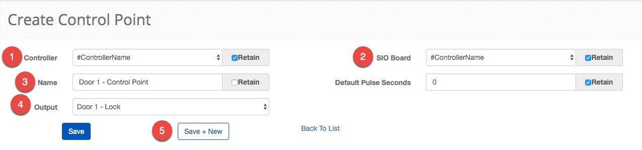
- Select #ControllerName from the Controller drop down menu.
- Select #ControllerName from the SIO Board drop down menu.
- Enter **"**Door 1 - Control Point" in the Name text field.
- Select Door 1 - Lock from the Output drop down menu.
- Use the button to continue onto the next Control Point.
Now, let's set up the last Control Point. With the retained field we should only have to enter a new name and select a different Output.
 Click to Enlarge
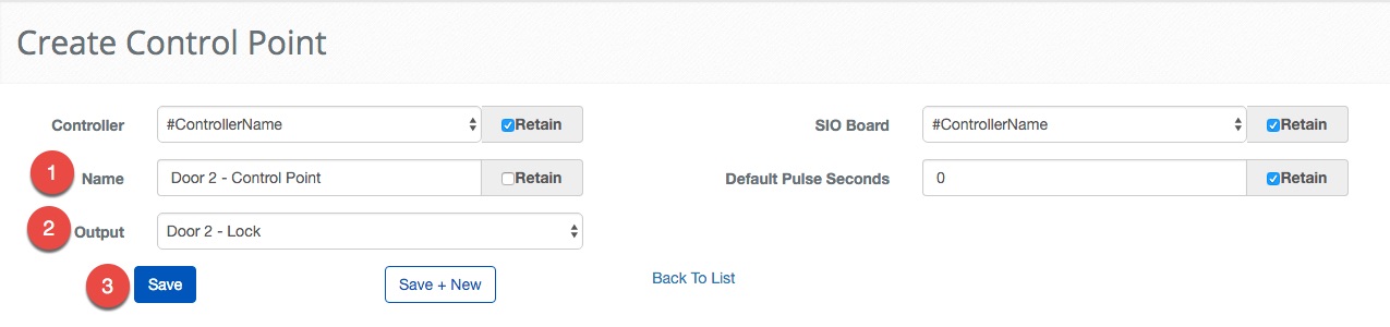
Some fields are retained from the previous configuration.
- Enter **"**Door 2 - Control Point" in the Name text field.
- Select Door 2 - Lock from the Output drop down menu.
- Click the button to finish the Control Point configuration.
Summary
To recap, we entered the information for the Customer, the organization that owns the access control system. We then configure the System in BluSKY and assign it to the newly created Customer. Next, we configured the Facility that will contain the System. This takes care of all of the base information we need about the System. We then moved on to configuring the Inputs, Outputs and Readers needed to configure a Portal. To finish we added two Control Points so that we can get the status of the Outputs for real-time control.
Now we have a system that is really secure but an access control system is more than just keeping people out. In the next portion of this demo we will begin adding the people and the organizations that will utilize the system.