Elevator Configuration - Setting up the I/O
Overview
We strongly recommend using the Retain and Save + New Feature. When configuring an Elevator there is typically a high amount of repetition and these features will help you save time and get a more accurate configuration.
Create Inputs
Depending on the needs of your customer, you may choose to decide to forgo creating the Elevator System with feedback. This is a cost-saving choice that you may decide to pursue. While the security implication is the same whether you choose to or not, there is a considerable hit when it comes to reporting. If the System is able to recognize the selected Floor it will be displayed in the Reports and more accurately in the Events screen. We can talk about how to configure the Inputs but ultimately the choice is between you and your Customer.
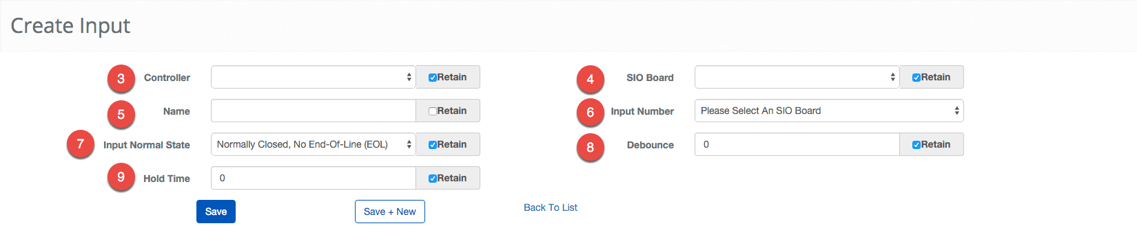
- Navigate to Inputs. Main Menu-> Setup-> System Setup-> Input
- Use the
 icon on the lower-left side to create a new Input.
 - Pick the Controller that manages the Input.
- Pick the SIO Board or the Controller the Input is physically attached to.
- Note: If the Input is connected directly to a Controller the Controller and SIO Board fields will have the same name.
- Next, choose a Name for the Input.
- Note: Using good names can make the process of servicing and debugging much easier.
- Select the Input Number that corresponds with where the Input is connected to on the SIO Board.
- Note: The physical board should be labeled with these numbers, if not use the official board documentation.
- Choose the Input Normal State from the dropdown menu.
- Set the Debounce.
- Set the Hold Time.
- Confirm the entry with the
 button or because of the nature of this job we provide a
  button to move onto the next entry quickly.
- Note: There are many more ways to configure a Controller the More...
 option will expand these options. This option should only be explored by trained technicians.
- Note: There are many more ways to configure a Controller the More...
Repeat this process as many times as needed to create all of the Inputs needed for the elevator system. Keep in mind, that the retain feature is a great way to speed this process up.
Create Outputs
Unlike Inputs, Outputs are absolutely required. It is important to remember that a relay-based system will use the Output to physically enable or disable the button inside the elevator.
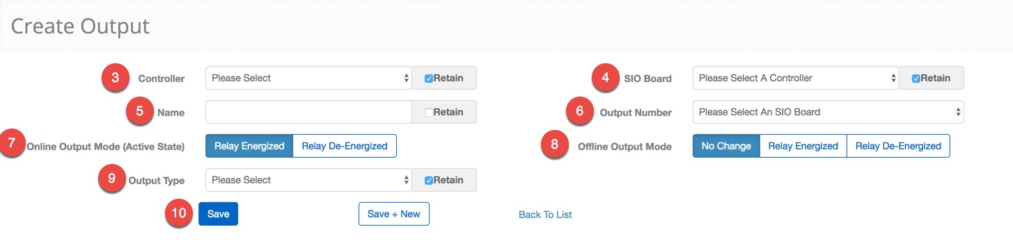
- Navigate to Outputs. Main Menu-> Setup-> System Setup-> Output
- Use the icon on the lower left side to create a new Output.
- Pick the Controller that will be used to manage the Output.
- Then select the SIO Board the Output is attached to.
- Note: In some cases, the SIO Board and Controller will be the same.
- Next, choose a Name for the Output.
- Note: Using good names can make the process of servicing and debugging much easier.
- Select the Output Number that corresponds with Output.
- Note: This is the number that corresponds with which connection is used on the board.
- Click on either the Relay Energized or the Relay De-Energized button for the Online Output Mode. This will determine how the Output should behave during normal operation.
- Ex. A magnetic lock would "Relay De-Energized" to cause the magnet to become inactive and release the door.
- Click on either No Change, Relay Energized or Relay De-Energized button to set the Offline Output Mode. This will determine how the Output behaves when it is unable to communicate with the Controller and is unable to verify credentials.
- Select the type of the Output from the Output Type drop-down menu.
- Confirm the entry with the button, alternatively, we provide a
 button to move onto the next entry quickly.
Repeat this process as many times as needed.
Create Readers
You still need to add Readers to the Elevators. This process is identical to creating Readers for Portals. You will need to configure at least one Reader per elevator car.
Wiegand Reader
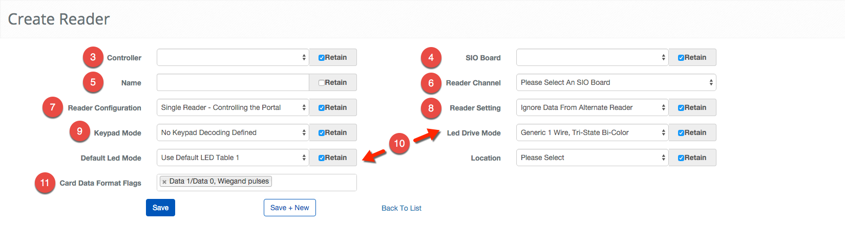
- Navigate to Readers. Main Menu-> Setup-> System Setup-> Readers
- Use the icon in the lower left side to create a new Reader.
- First, pick the Controller that will manage the Reader.
- Select the SIO Board the Reader is attached.
- Note: In some situations the SIO Board and Controller will be the same.
- Enter a name for the Reader in the Name text field.
- Note: Using good names can make the process of servicing and debugging much easier.
- Select the Reader Channel that corresponds with the Reader port on the SIO Board or Controller.
- Note: This is the number that corresponds with which connection is used on the board.
- Choose the Reader Configuration.
- Choose the Reader Setting from the dropdown menu.
- Choose the Keypad Mode.
- Select the appropriate LED Drive Mode and Default LED Mode.
- Click in the Card Data Format Flags field to bring up list of applicable Format Flags.
- Confirm the entry with the button or because of the nature of this operation we provide a button to move onto the next entry quickly.
OSDP Reader
- Navigate to Readers. Main Menu-> Setup-> System Setup-> Readers
- Use the icon in the lower left side to create a new Reader.
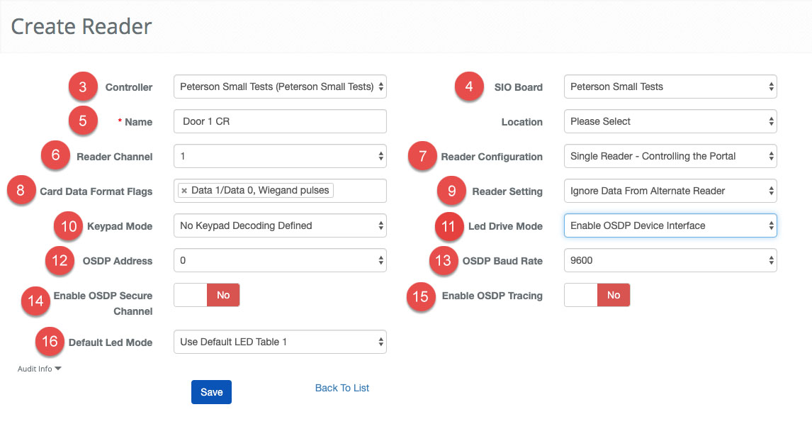
- First, pick the Controller that will manage the Reader.
- Select the SIO Board the Reader is attached.
- Note: In some situations the SIO Board and Controller will be the same.
- Enter a name for the Reader in the Name text field.
- Note: Using good names can make the process of servicing and debugging much easier.
- Select the Reader Channel that corresponds with the Reader port on the SIO Board or Controller.
- Note: This is the number that corresponds with which connection is used on the board.
- Choose the Reader Configuration.
- Click in the Card Data Format Flags field to bring up list of applicable Format Flags.
- Choose the Reader Setting from the dropdown menu.
- Choose the Keypad Mode.
- Select the appropriate Led Drive Mode set to OSDP Device Interface
- OSDP Address - Select the channel the reader is configured for. Most single OSDP Readers are 0. You can purchase readers with different channel numbers, and there are reader configuration cards that will change the channel. If you do not know your channel start with 0 and work your way up. Note: WIth OSDP you can now "daisy-chain" 4 readers to a single reader port on the SIO board.
- Set the OSDP Baud Rate - 4 speed options 9600 (default) 19200, 38400, 115200
- Enable OSDP Secure Channel allows for secure communication from Controller to Reader
- Enable OSDP Tracing This should be set to "No" unless directed by BluB0X support. This setting will add OSDP reader information to Mercury debug logs, which would also need to be manually configured by BluB0X Support.
- Click in the Default LED Mode field to bring up list of applicable modes.
- Confirm the entry with the button or because of the nature of this operation we provide a button to move onto the next entry quickly.
Summary
In this part of the tutorial, we go through creating all of the separate pieces that will be used to operate and secure the elevators. In the next step, we will start grouping the pieces together to define the equipment that is used in each of the Elevators.